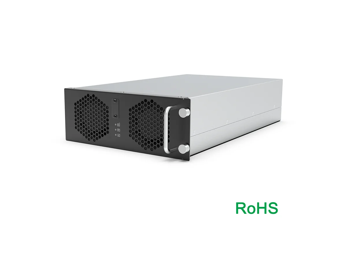
Introduction: The Fast-Charge Stop That Shouldn’t Take All Day
You pull into a busy site with five minutes to spare and two hungry kids in the back. A liquid cooling module is the quiet hero you never see, keeping the charger calm when the lines get long. With liquid cooled ultra-fast charging, that short stop can stay short—even when the sun hits hard. Many hubs face 35–45°C heat, and fan-only cabinets can derate by 20–30% at those temps. That’s real time lost (no shade, kids get restless fast). So why do some “350 kW” stations drop to half power right when you need the speed most?
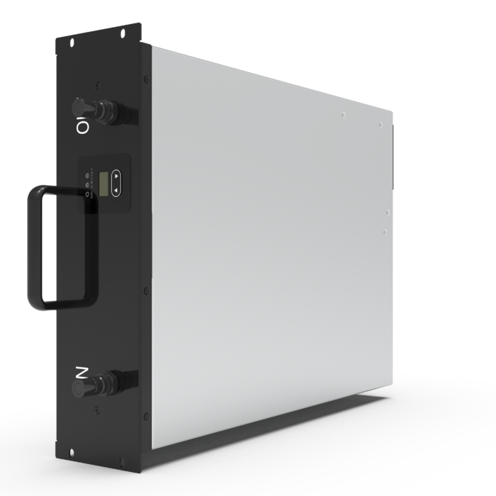
Here’s the core idea in plain words. Heat slows the power converters that turn grid AC into DC for your battery. When airflow meets dust and hotspots, high-current parts run hot, and safety rules kick in. Power falls. Queues grow. Sound familiar? The question is not only “how fast” but “how stable under stress.” And that’s where design choices—air vs. liquid—make all the difference. Let’s set the stage for what fails first, and how to fix it next.
Traditional Air Cooling: The Hidden Weak Links
Why do air systems stumble?
Air is fine until it meets dust, noise limits, and summer heat. In many cabinets, fans push across heat sinks, but hotspots build around SiC MOSFETs and the DC bus. As ambient rises, airflow does less per degree. Filters clog. Thermal resistance climbs. Derating follows. Look, it’s simpler than you think: less steady heat out means less steady power out. By contrast, liquid cooled ultra-fast charging moves heat to a compact heat exchanger, so components see a tighter temperature band. That steadies the rectifier stage and keeps switching parts inside their comfort zone.
Air systems also spread heat unevenly. One module cooks while its neighbor idles, and the whole stack slows to protect the worst spot. Liquid loops even out that map. A cold plate sits on the parts that run hottest, and the coolant loop carries energy away at a stable rate. This protects power converters under peak load and cuts fan noise. Edge computing nodes near sites face the same physics, and the lesson repeats: control the gradient, protect uptime. It is not magic—just better heat paths.
From Principles to Practice: What’s Next for Liquid-Cooled Fast Charging
Real-world Impact
New designs follow simple physics. Move heat by liquid, not air alone. Keep the loop sealed. Place the heat exchanger where airflow is clean and service is safe. Use variable-speed pumps so flow tracks load. When you pair a liquid cold plate with a high-voltage bus, losses drop and components live easier—funny how that works, right? The 1000V charging module path also reduces current, which lowers I²R heating in cables and busbars. That means smaller temperature swings across the cabinet, fewer nuisance trips, and better MTBF. In short, the new principle is stability first. Stable temperatures yield stable power, even at 40°C ambient and sustained load.
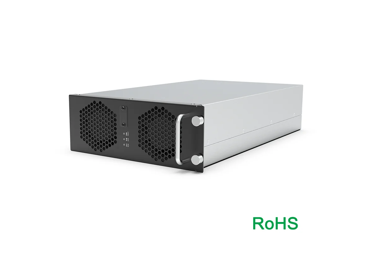
So how do you choose a system that proves it on the curb, not just on a slide? Use three checks. First, measure temperature rise per kilowatt at 35–45°C ambient; target a tight delta-T under continuous load. Second, look at lifecycle: pump rated life, coolant interval, and MTBF for key modules. Third, test for steady output under worst-case noise and dust: IP rating, acoustic limits, and derating curves under clogged-filter scenarios. If a design holds its line there, it will hold it anywhere. That’s the practical yardstick for fleets, corridors, and city hubs—the places where uptime pays back every hour. For deeper specs and platform examples, see resources from winline technology.